
Thank you! Your submission has been received!
Oops! Something went wrong while submitting the form.
Coupon1
Coupon2
Cart note
A basic overview of the forces associated with straight and level flight, climbs, descents, and turns.
4 FORCES OF FLIGHT
Lift, Weight, Thrust and Drag
STRAIGHT AND LEVEL FLIGHT
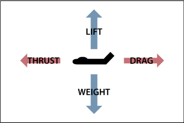
In straight and level flight, lift is equal to weight and thrust is equal to drag. Airspeed and altitude do not change.
Note: Whether in straight and level flight, a climb, or a descent, weight always points directly down, toward the center of the Earth, due to gravity.
CLIMBS
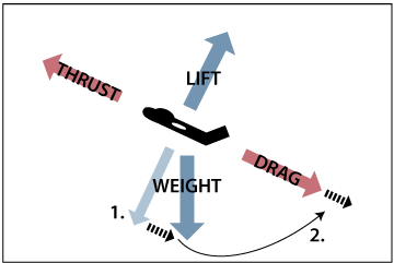
If a climb is entered with no change in the power setting, airspeed will diminish.
1. Notice how the weight vector moves in relation to the aircraft between level flight (shown with the light blue arrow), and the climb (dark blue arrow). As the aircraft pitches up, weight continues to point straight down and essentially moves backward from where it was in level flight (shown by the dashed black line).
2. When inclined upward, this rearward movement of weight acts in the same direction as drag, and has the same effect as increased drag. Without a corresponding increase in thrust, there is now more drag than thrust, and the aircraft slows until the forces are balanced again. Therefore, in order to maintain airspeed in a climb, thrust must be increased.
DESCENTS

If a descent is entered with no change in the power setting, airspeed will increase.
1. Notice how the weight vector moves in relation to the aircraft between level flight (shown with the light blue arrow), and the descent (dark blue arrow). As the aircraft pitches down, weight continues to point straight down and essentially moves forward from where it was in level flight (shown by the dashed black line).
2. When the aircraft is pitched down, this forward movement of weight acts in the same direction as thrust, and has the same effect as increased thrust. Without a corresponding decrease in thrust, the thrust vector outweighs the drag vector, and the aircraft accelerates until the forces are balanced again. Therefore, reduced thrust (or increased drag) is needed to maintain a consistent airspeed during a descent.
STRAIGHT AND LEVEL
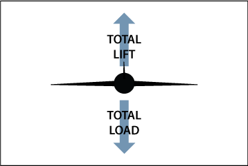
As shown above, in straight and level flight, lift is equal to weight (or load). When the aircraft is banked, the total lift and total load rolls with the aircraft while weight continues to point toward the center of the Earth (as shown in the next two graphics).
As an aircraft banks, the total lift vector is divided into 2 components, a Vertical Component of Lift (VCL), as well as a Horizontal Component of Lift (HCL). The VCL is opposed by Weight, and the HCL is opposed by Centrifugal Force.
When these forces are balanced, Total Lift is equal to Total Load, and the aircraft maintains a level, coordinated turn. In this section, we'll assume a coordinated turn (HCL = CF), and look at why back pressure is required in a turn (VCL vs Weight).
LEFT BANK, NO BACK PRESSURE
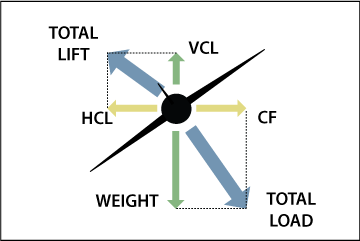
Lets imagine we roll into a 30 degree coordinated left turn without adding any back elevator pressure. As the aircraft rolls, the total lift we saw in the first diagram is divided into a VCL (green) and HCL (yellow). The greater the bank angle, the greater the HCL, and the smaller the VCL. Because the weight of the aircraft is unchanged, and weight now exceeds the VCL, the aircraft will descend.
In order to compensate for the loss in vertical lift, the VCL must be increased with the elevator. Altitude is maintained when the VCL is equal to weight (as shown in the next graphic). When the VCL is equal to Weight and the HCL is equal to the CF, Total Lift becomes equal to the Total Load on the aircraft, and a level, coordinated turn is made.
LEFT BANK WITH BACK PRESSURE
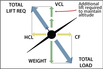
In a level, coordinated turn:
To summarize, back elevator pressure is required to compensate for the portion of vertical lift that has been transferred horizontally, and maintain altitude in a turn.
COORDINATED TURN
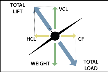
As mentioned above, in a turn some VL becomes HL. As you may remember, from Newton's 3rd Law, every force has an opposing force. The force opposite the HCL is called Centrifugal Force (CF).
As shown in the graphic above, a turn is coordinated when the HCL is equal in strength to the CF opposing it. If the HCL is not equal to the CF the turn will not be coordinated.
SLIPPING TURN

In a slipping turn, the HCL is greater than the CF. This is because the rate of turn is too slow for the angle of bank. The aircraft is yawed to the outside of the turning flight path in a slipping turn.
A slipping turn can be corrected by decreasing the angle of bank and/or increasing the rate of turn (increased rudder in the direction of the turn).
SKIDDING TURN
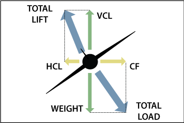
In a skidding turn, the CF is greater than the HCL. This is because the rate of turn is too great for the angle of bank. The aircraft is yawed to the inside of the turning flight path in a skidding turn.
A skidding turn can be corrected by reducing rudder in the direction of the turn, and/or increasing the bank angle.
An overview of the critical engine discussing what the critical engine is, which engine is the critical engine, and the reasons why it is the critical engine.
1. WHAT IS THE CRITICAL ENGINE?
The critical engine is the engine that if failed will have the most adverse affect on the CONTROL and PERFORMANCE of the aircraft.
2. WHICH ENGINE IS THE CRITICAL ENGINE?
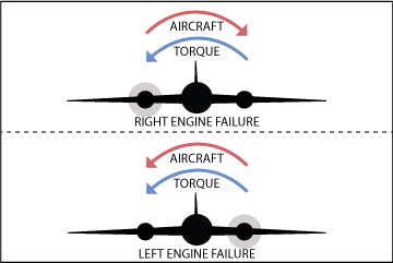
In a conventional twin (clockwise prop rotation), the LEFT ENGINE is the critical engine.
In a counter rotating twin, there is no critical engine.
3. WHY IS THE LEFT ENGINE CRITICAL?
There are 4 reasons the left engine is the critical engine (REMEMBER - PAST):
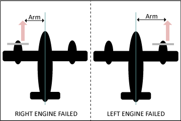
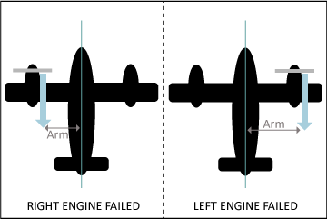
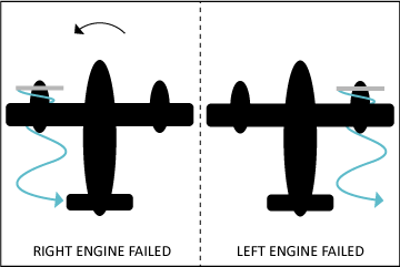
Here we'll break down VMC - what it is, how it works, and what can affect the minimum controllable airspeed.
Ready to teach this concept like a pro? Download Nate’s MEI Lesson Plans
Published Vmc (in your POH) is the speed at which the rudder no longer has the authority to overcome the yaw caused by the critical engine being inoperative, under specific criteria mandated by the FAA.
The lower Vmc is, the safer the aircraft is. It makes sense that the slower an aircraft can go while still maintaining control with an engine failed, the better.
Vmc strictly deals with maintaining directional control, irrespective of climb performance.
Keep in mind that published Vmc (in your POH / the red line on your airspeed indicator) is based on the specific conditions and criteria mandated by the FAA, whereas actual Vmc will vary based on the actual conditions during the engine failure.
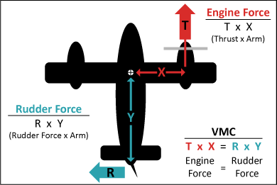
Say, for example, an operating engine at max thrust produces 1,000 lbs of yaw (T x X) toward the dead engine. This force will remain consistent regardless of airspeed. Now, assume that at 150 kts the rudder can produce 2,000 lbs of force (R x Y). As airspeed is reduced, so is the rudder’s force. At 100 kts, this rudder can generate 1,400 lbs of force, more than enough to control the 1,000 lbs from the failed engine. But, as airspeed continues to decrease, the rudder will reach a point, say 70 knots, at which it can produce exactly 1,000 lbs (the same as the yaw from the engine). This is the minimum controllable airspeed. As soon as the aircraft decelerates below 70 kts the rudder’s force drops below 1,000 lbs. At this point, the rudder is unable to overcome the yaw caused by the engine being inoperative and the aircraft begins an uncontrollable yaw toward the dead engine. If the airspeed is increased, or thrust is reduced on the operating engine, the rudder can regain control.

The FAA sets forth criteria for aircraft manufacturers to follow in order to establish Vmc for an aircraft. The criteria is as follows:
MAXIMUM TAKEOFF POWER - BAD for Vmc
The more power on the operating engine, the greater the force pulling toward the dead engine. The greater the force, the earlier the rudder will lose control. The minimum controllable airspeed will be higher with greater power.
CRITICAL ENGINE INOPERATIVE - BAD for Vmc
The critical engine is the engine that has the most adverse affect on control of the plane. By failing this engine, the rudder has more force to overcome than if the R-engine was failed, therefore Vmc will be higher.
INOPERATIVE ENGINE WINDMILLING - BAD for Vmc
A windmilling prop creates more drag than a feathered prop. Increased drag on the inoperative engine will create a stronger yaw toward the dead engine. Therefore, the rudder has to overcome more force, raising Vmc.
SEA LEVEL CONDITIONS - BAD for Vmc
At sea level the dense air allows the operating engine and prop to produce maximum thrust. Since there is more thrust, there is a greater force toward the dead engine for the rudder to overcome, therefore Vmc is higher.
MOST UNFAVORABLE LEGAL WEIGHT (LIGHTEST WEIGHT) -BAD for Vmc
Vmc increases as weight is reduced so the lightest legal weight is most unfavorable. The lightest weight provides the aircraft the least momentum. The heavier the aircraft, the more likely its inertia will carry it forward and help prevent the yaw and roll associated with a failed engine.
MOST UNFAVORABLE LEGAL CENTER OF GRAVITY (AFT CG) -BAD for VMC
Vmc increases as the C of G is moved aft. The further aft the C of G, the shorter the rudder’s arm is. The shorter the arm, the less effective the rudder. Vmc will be higher since the rudder produces less force at any speed than if the C of G was forward.
OUT OF GROUND EFFECT -BAD for Vmc
Vmc decreases in ground effect. As the aircraft yaws and rolls toward the dead engine the dead engine’s wing would dip further into ground effect, reducing its drag as it became more efficient, thus reducing the yaw toward the dead engine.
GEAR RETRACTED - BAD for Vmc
When the gear is down it acts as a keel (like on a boat) which aids in directional stability and decreases Vmc. With the gear up the keel effect is removed and it cannot help keep the aircraft straight.
COWL FLAPS OPEN - GOOD for Vmc
With the cowl flaps open the operating engine’s prop will push air into the cowl flaps resulting in increased drag. Increased drag on the operating engine decreases Vmc since it assists in counteracting the yaw toward the dead engine.
5 DEGREES OF BANK INTO THE OPERATING ENGINE - GOOD for Vmc
The horizontal component of lift generated by bank assists the rudder in counteracting the yaw from the inoperative engine. Vmc is reduced considerably with bank angle so the FAA limits the bank during testing to 5 degrees.
FLAPS IN THE TAKEOFF POSITION - Could go either way
Most twins takeoff without flaps, therefore there will be no effect. But, with many different flap sizes, types, and settings, having the flaps down could help or hurt Vmc. Having the flaps down could produce more drag on the operating engine
(reducing the yaw), it could also create more lift on the operating engine’s wing (increasing roll toward the dead engine).
Fly Further, Faster—Starting Today - Get the Lesson Plans
CRITICAL ENGINE
The engine that if failed will have the most adverse affect on the control and performance of the aircraft.
A Breakdown of the Critical Engine...
Vmc
The speed at which the rudder no longer has the authority to overcome the yaw caused by the critical engine being inoperative, under specific criteria.
A Breakdown of Vmc...
ACCELERATE STOP DISTANCE
The distance required to accelerate to rotation speed, and assuming an engine failure at rotation, bring the aircraft to a stop. This is the maximum runway required for an aborted takeoff since an engine failure after rotation will be handled airborne.
ACCELERATE GO DISTANCE
The distance required to accelerate to rotation speed, and assuming an engine failure at rotation, climb to 35’ above the departure end.
SERVICE CEILING
The density altitude which will produce a 100 foot per minute climb when flying in a clean configuration, at the best rate of climb airspeed with both engines at maximum continuous power.
SINGLE ENGINE SERVICE CEILING
The density altitude which will produce a 50 foot per minute climb when flying in a clean configuration, at the best rate of climb airspeed with one engine at maximum continuous power and the other engine feathered.
ABSOLUTE CEILING
The highest altitude at which an airplane can sustain level flight with both engines operating (this altitude will never be reached in flight except during flight testing).
SINGLE ENGINE ABSOLUTE CEILING
The highest altitude at which an airplane can sustain level flight with one engine operating. This altitude will only be reached if flying above the single engine absolute ceiling when the engine is lost and the aircraft drifts down to the SE absolute ceiling.
CRITICAL ALTITUDE
The maximum altitude under standard atmospheric conditions at which a turbocharged engine can produce its rated horsepower. Above this altitude, the engine‘s performance will begin to decrease.
Vyse
The best rate of climb airspeed during single engine operations.
Vsse
The safe single engine speed. It is unsafe to intentionally fail an engine below this airspeed.

.jpeg)